1. Fault Phenomenon
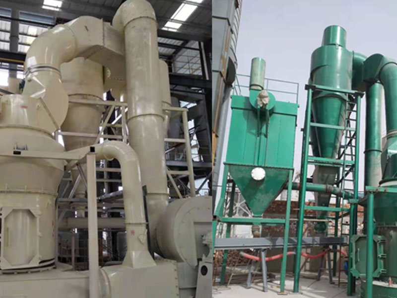
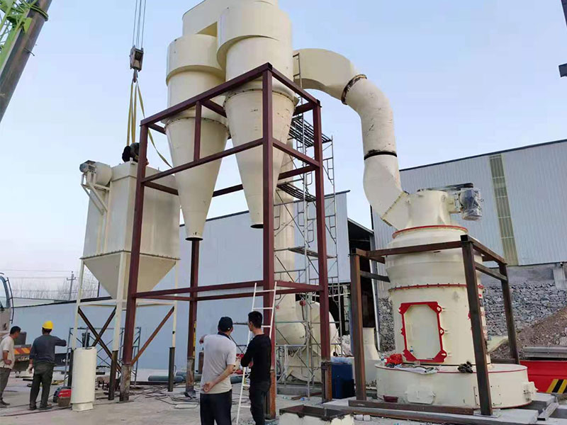
In September 2014, during the external circulation discharge operation of a fly ash steel silo project, the dust collector motor at the top of the silo frequently tripped due to faults, causing the dust collector to stop functioning. The on-site staff reported the following conditions:- During startup, the dust collector motor occasionally tripped due to a fault.
- After about 1–2 hours of external circulation discharge operation inside the steel silo, the dust collector motor tripped.
- When the motor tripped, the motor protector displayed an operating current of 40A.
- The dust collector on site was a PPCS32-6 model, with the following nameplate data:
2. Root Cause Investigation and Data Recording
Based on the feedback from the site, our company immediately dispatched relevant professionals to investigate the cause of the fault from the following aspects.2.1 Mechanical Inspection
- Whether the coupling installation between the motor and reducer met the standard.
- Whether there was any scraping or friction when manually rotating the fan rotor.
- Whether the oil level of the reducer bearing was normal.
- Whether the dust collector filter bags were damaged.
- Whether the delivered equipment parameters were consistent with the design parameters.
2.2 Electrical Inspection
- Use an insulation resistance tester to check whether the insulation of the cable and motor met the requirements.
- Check whether the cable connections were firm and whether there was any poor contact.
- Check the parameter settings of the motor protector.
2.3 Recording Relevant Operating Data
After inspection by equipment engineers, no issues were found in the mechanical part. In the electrical part, there were also no problems with cable and motor insulation or cable connections. Since the dust collector occasionally tripped during startup, in order to ensure smooth startup and record operating data, the motor protector action current was adjusted from the original 36A to 40A (that is, 1.1 times the rated current of the motor). The operating data recorded were as follows:- Power supply inlet voltage when equipment was not running:
- Data after 4 hours of no-load operation of the dust collector:
- Data after 90 minutes of dust collector operation during external circulation discharge of the steel silo:
3. Cause Analysis
Based on the above data analysis and clamp meter testing, it was found that during the external circulation discharge operation of the steel silo, the three-phase power supply voltage dropped from about 398V under no-load conditions to about 354V under load. At the same time, the motor current and motor temperature rose slightly compared with no-load conditions. According to GB 50052-2009 Code for Design of Electric Power Supply Systems, under normal operating conditions, the allowable voltage deviation at the motor terminal is ±5% of the motor rated voltage. It can therefore be seen that the actual operating voltage of the dust collector motor on site was far lower than its rated voltage, with a voltage deviation of about -11%, which could no longer meet the allowable deviation requirement of ±5% specified in GB 50052-2009. According to the power calculation formula: P = √3UIcosφ when the supply voltage dropped to 354V, the motor current directly increased to about 40A. At this point, the actual motor current had exceeded the motor protector setting of 36A, so the motor protector activated overcurrent protection and tripped. Note: During external circulation of silo material, the dust collector motor was controlled by a motor protector, while the other equipment was controlled by variable frequency drives. After inspection, the reasons for the low power supply voltage of the dust collector motor were identified as follows:- The incoming power supply to the steel silo electrical room was a temporary power source, and the distance from the source point to the steel silo electrical room was about 500m.
- If only a single piece of equipment was operating, the power supply provided by the steel silo electrical room met the equipment requirements. However, during external circulation discharge, the operating equipment included:
- Since this project was under construction, other temporary electrical equipment on site was also drawing power from the steel silo electrical room. It was highly likely that temporary equipment and the external circulation system were operating simultaneously.
4. Countermeasures and Results
The solution was to replace the source point of the main incoming power supply to the steel silo electrical room as soon as possible. Before the new power source was connected, simultaneous operation of electrical equipment was prohibited. In November 2014, the newly constructed substation officially went into operation. The power supply of the steel silo electrical room was changed to be introduced from the grinding electrical room, and the distance from the grinding electrical room to the steel silo electrical room was about 60m. After the formal power supply was connected to the steel silo electrical room using cables of the same model and specification as the temporary power cables, the supply voltage during external circulation discharge remained stable at 390–399V. The on-site equipment then operated normally, and the dust collector motor no longer experienced overcurrent tripping.This article was published on May 22, 2026, and last updated on May 22, 2026. The article will be continuously updated.